
Making PippyG cases
On this page we cover instructions for making weather-proof DIY cases for the PippyG (and Audiomoth):
- Materials and tools required
- Preparation for case building
- Making the OBO Bettermann A8 Case
- Making the “Type F with Ears”
We would love to hear your experiences or questions, please do contact us, or post a message on our Facebook Group.
1. Materials and tools required
Case
There are two case designs that make excellent starting points. We covered the good and bad points of each on this page. Choose whichever best suits you.
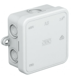
OBO Bettermann A8 Junction Box
This is a well tried and tested design and fits all versions of PippyG and AudioMoth. Widely available from many stores, including Amazon
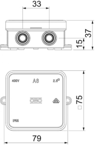
Size in mm = 75w x 75d x 37h.
Another source is Toolstation in the UK, who sell a very similar clone of this box.
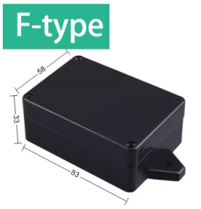
A stronger, smaller and more sealed box. It only fits PippyG 4.x and AudioMoth v1.1+. Can be harder to find online, as often out of stock on AliExpress or eBay (eps.. black).
Search for: “Case 83x58x33”
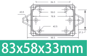
Size in mm = 83w x 58d x 33h
Stainless steel mesh
For making the case covering for the microphone hole. We recommend two layers of 316 Stainless Steel mesh, coated to make them Hydrophobic:
- Fine 400 gauge, 400 wires per inch, 35 micron holes – For the covering nearest the mic hole
- Coarser 80 gauge, 80 wires per inch, ~175 micron holes – As a cover to deflect high energy raindrops from the fine mesh
We have done a lot of testing to arrive at these recommendations, click here for details:
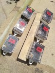
During the first Covid lockdowns in 2020 we had time to do a lot of weather proof testing of variations for AudioMoth cases. We tested for the worst case of wind driven rain by placing the test cases at between 60 to 30 degrees to the horizontal, and had multiple cases all of different configurations of mesh out at the same time. We prayed for rain, as much as possible…
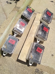
Our results can be summarised as:
- Using a single layer of mesh, the cases were always wet. The best were 500 and 400 gauge, then getting wetter at 325 gauge, and the worst at 200 gauge.
- Using hotmelt glue, or epoxy resin to attach the mesh, gives fair worse results than Gorillia mounting tape. Glued vent cases are ALWAYS wet.
- Using a second layer of mesh to absorb high energy raindrops works, with similar results from 80 to 500 gauge. 40 gauge failed, and if anything made the case wetter.
- Using Cloth camo tape near the mesh vent does seem to help. Perhaps by wicking water away from the mesh, or maybe slowing down water as it runs down the face of the case.
There are many suppliers online, but we have found inoxia.co.uk to offer quick delivery on small quantities at cheap prices. A 15 x 15cm sheet at £1.99 will do hundreds of cases. But if you are only doing one or two, you may be able to get away with a “free” sample sizes for £2.50 p&p 🙂
When the mesh arrives, make it hydrophobic (water repelling) by applying a soaking of a waterproof product such as NicWax or similar, and allow it to dry overnight before using.
Double sided tape
To mount the mesh over the mic hole we use three layers of clear 25mm wide double sided tape 1mm thick. There are lots of options, but back in 2019 we started using “Gorilla Crystal Clear Mounting Tape 25mm” x 1.5m roll, and have stuck with it (literally). But there will be cheaper options.
If you are building the tight version of the”F Type” case we also suggest a small roll of 10mm wide double sided tape. You could get away with cutting down the 25mm tape, but it tends to make a sticky mess!
Double sided pads
Double sided pads 2mm or 3mm thick are cut to shape to locate the PippyG in the lid of the case. Widely available these are often branded 3M, in many sizes and shapes. We like these, as they reduce the amount of cutting required.
Foam Mat
Small offcuts from a thin foam mat, such as a camping or yoga mat, are used to pad the bottom of the case. Ideally you are looking for a really (cheap) thin mat around 7mm thick.
If building the “Type F with ears” tight fit versions of the case, you may also need a tiny amount of a more “squashy” 8mm thick foam or sponge (or 10mm thick cut to a 8mm wide strip).
Camo Tape
This is optional, but if you want to hide your PippyG or AudioMoth away from the publics gaze it can be very useful. You are looking for “Self-adhesive Waterproof Cloth Camo Tape“, it comes in several designs usually in a 50mm wide roll, 5 m or 10m long.
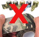
You do NOT want the type of elastic camo wrap that is sold for covering outdoor equipment like rifles. This is stretchy and self conforming, only sticking to itself. Hence it is only useful for “wrapping” things.

Tools
Just basic craft tools are required:
- Sharp craft knife such as a scalpel
- Self healing cutting mat
- Straight edge ruler, ideally metal
- Scissors
- Cordless drill with HSS drill bits – 3mm, 6mm (and 1.5mm)
2. Preparation for case building
Which ever case you are building there are a couple of jobs to do first
PippyG – Make a template for the mic hole
To ensure you align the microphone of the Pippyg accurately with the vent hole in the case, it is necessary to sacrifice one of your PippyG boards. Drill out the mic hole with a 3mm high speed drill. To accurately enlarge the mic hole from 0.7mm, we first like to drill with a 1.5mm drill, then enlarge with a 3mm drill.
This then becomes your Mic hole template for all future case builds.
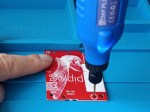
Experience has taught us that is well worth writing on the Mic Hole temple, both which version of the PippyG it is for, and also to mark clearly on the back which hole needs to be drilled for the microphone. Daft as it sounds, with the several mounting holes in the PippyG v4.04 its very easy to drill the wrong hole. (yes, we have done it…)
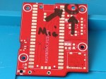
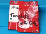
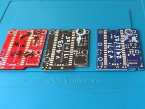
It is worth mentioning that Phil and Apodemus have moved the mic hole around…
- PippyG v 3.71 and earlier, and the Apodemus Pippyg1 are the same.
- PippyG v4.0 and later, moved the Mic about 1.3 m towards the top of the board.
- The Apodemus Pippyg2 appears to have moved the mic more central.
- The AudioMoth mics have not moved, but are located in a different corner to all above.
The result of this is that, for each of the types above will need to make a different case. 😒
Apodemus PippyG or AudioMoth
Lastly if you are make a case for the Apodemus PippyG or AudioMoth, you will not be able to sacrifice a board to make a template, and hence you will have to rely on measurement. Good luck! It’s not easy. The best advice is to measure twice, and drill once, with a small drill first to check for position.
Click here for more details of the Apodemus PippyG.
Elmar Jongerius the Product Design Manager at Apodemus, recently said on the BatDetectorists Facebook Group:
“(Apodemus PippyG) do have the same board size (as PippyG 3.71). However the (Apodemus) Pippyg2 is a bit less thick (no modules anymore).
The Pippyg2 has the ability to unscrew the battery holder, then fold away and access the board. This makes the mounting pattern for the acoustic horn accessible, and allows for precise (and this is upmost important) alignment and sealing.”
The result of this is that the Apodemus PippyG 1 (25mm deep) will probably fit in a DIY PippyG3.71 case without modification. Click here for the technical drawing of the Apodemus PippyG 1.
Whereas the Apodemus PippyG 2 (22mm deep), with a more central Mic, will either need the custom Apodemus case, or a special DIY using the OBO Bettermann A8 and thicker 10 to 11mm foam in the base. Click here for the technical drawing of the Apodemus PippyG 2.
Treat the Stainless Steel Mesh
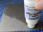
When your mesh arrives the first thing to do is to make it hydrophobic (water repelling) by applying a soaking of a waterproof product such as NicWax or similar.
Flood both gauges of mesh with the waterproofer, then shake or blot off the excess, and allow it to dry overnight before using.
3. Making the OBO Bettermann A8 Case
This push fit case is “universal”, it is slightly bigger so can be used with all PippyG (including Apodemus) and all AudioMoths. However as the Mic hole position varies a lot between these devices, once made it is specific to a type of device.
The process consists of two parts:
- Fitting the device into the lid of the case, and make the vent for the mic.
- Padding the bottom of the case to ensure the device stays in close contact with the lid
Start with the lid:
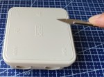
1. Shave lip – The top of the lid of the A8 has raised writing, symbols and a edge lip on it. To ensure the mic vent has a good seal it is a good idea to use a scalpel to carefully shave off and remove the raised lip, where the mic vent will go. This is the bottom left corner of the lid under the VDE triangle symbol.
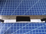
2. Cut foam strips to locate PCB – Using a cutting mat, scalpel and metal ruler, cut the self adhesive double sided foam into 8mm wide strips. As the backing of the foam is slippery and moves easily, for accurate cuts we find it useful to temporarily tape the foam to the back of the ruler using small bits of gaffer tape, and to use extra foam to support the ruler and keep it level. An alternate worth trying is VERY sharp scissors (like dressmaking scissors).

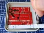
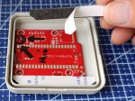
3. Place foam in lid to locate PCB – Turn the lid upside down, and place the Mic template PCB in the middle of the lid, with the top of the PCB up against the bottom of the lid. Take a 8mm foam strip and cut to the length of one side. We find this easiest by placing and using the scalpel to mark it. Cut the corners of the foam to fit the case, and test fit. If happy, peal the backing from the bottom of the foam and stick into place. Do NOT remove the top backing of the foam.
Repeat for the other two sides, and when done ensure the PCB is snugly, but not tightly held.
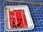
4. Drill Mic Hole – Using a 3mm HSS drill straight down thought the lid, through the correct hole on the mic hole template.
After drilling using a scalpel tidy up the edges of the hole. A slight (1mm) countersinking on the outside of the hole is a good idea.

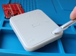
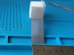
5. Cut the 80 s/s mesh – The 80 gauge stainless steel mesh is used to absorb the energy of high velocity water drops. Using scissors, cut a 25mm wide strip of the 80 mesh.
From this strip cut a pentagon (house shape), a 25 x 25mm square with a 7mm high Isosceles triangle on top (see photo). The triangle shows which way up, and helps deflect water running down the face of the case.
This 80 gauge pentagon (house shape) becomes your template for the next stage.
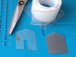
6. Cut mounts – Use the 80 gauge mesh as a template, and using scissors cut two similarly shaped sections of the 25mm double sided mounting tape.
It is FAR easier to do this if you first stick some of the own tapes spare backing to the end of the roll first. If you have made a case before you will already have these backings. But if its your first case it is well worth sacrificing the first 35mm of the tape to get to reusable backings.
Then cut a 6mm wide by 12mm high slot out of the bottom (not triangle) sides of these mounts. This is to allow any water that does get though the mesh to drain out downwards.

7. Place 400 mesh s/s mesh – Remove (and keep) the backing from one of the mounts, then place it over the mic hole as shown in the photo press down firmly. Remove the top layer of the mounting tape backing (this is quite tricky!), again keeping the backing.
Cut a 12mm square out of the 400 gauge stainless steel mesh and place it onto the mount so it is central over the microphone hole. Press down carefully, avoiding the adhesive.

8. Place 2nd mount – Remove the backing from the underside of the second mount and place it exactly over the first mount. Take care, as you one get one go at this.
Note: The slot on the second mount in the photo is a little deep. Ideally with a shorter slot, more of the second mount would overlap the 400 s/s mesh for a better seal.

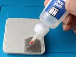
9. Place and glue top mesh – Remove the backing from the top of the second mount, and press the 80 gauge s/s mesh firmly into place. As the mesh is treated, you will find it does not stick that well. Hence we run a bead of superglue around the three top and side edges of the 80 mesh, and allow this to dry thoroughly (make take several hours).
..
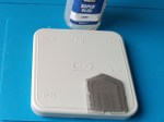
Having finished the lid it is time to move onto the base, which is a LOT easier!
10. Cut out 8mm foam for base – Using the upturned base of the case push it down into the 8mm thick foam sheet. This will make an indentation that you can cut around with scissors.
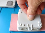
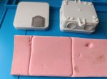
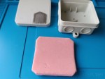
11. Fit foam into base of case – Take the cut piece of 8MM foam and push it upside down into the base of the case, press hard.
Using a scalpel cut out the marked areas, to allow for the indentations in the base. Then push fit the foam into the base, it should be a tight fit so no need for glue.
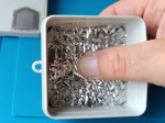
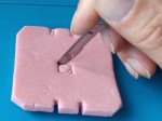

Finished A8 cases below. It is possible to cover the OBO Bettermann with Camo tape, but it is tricky. For best results use a scalpel (and patience!) to remove as many of the protrusions from the case as you can, before taping. If you don’t do this the tape will quickly part company with the case when exposed to the elements.

4. Making the “Type F with Ears” Case
This screw together case is stronger and smaller, it can only be used with DIY PippyG version 4.0.x and later (narrower board), or AudioMoth v1.1 or later (recessed switch).
As the A8 before, the process consists of two parts:
- Fitting the device into the lid of the case, and make the vent for the mic.
- Padding the bottom of the case and enlarging the mounting holes.
Start with the lid:
1. Waterproof seal – The cases waterproof seal comes loose inside the case, it is white silicone rubber and round in section. Push it into the groove on the lid.

1. (optional) Cut 10mm foam strips to locate PCB – If using 10mm high foam you can go straight onto step 2. Otherwise using a cutting mat, scalpel and metal ruler, cut the self adhesive double sided foam into 10mm wide strips. An alternate worth trying is VERY sharp scissors (like dressmaking scissors).
Tips for cutting 10mm wide strips with scalpel
As the backing of the foam is slippery and moves easily, for accurate cuts we find it useful to temporarily tape the foam to the back of the ruler using small bits of gaffer tape, and to use extra foam to support the ruler and keep it level.
Then there are two options for aligning the PippyG in the lid, either:
- Lid design A – Loose fit Using two flat foam pads. The advantage is no stress is placed on the battery pack. However closing the case is harder as the device will fall out when inverted, and the screws fall out if not!
The PippyG v4.04 was designed with locating holes for the 3D print (at our request), and hence the battery pack is now being much firmly attached. However we still tend to prefer this loose fit method, as we think its better than repeatedly repairing the hot glue on PippyGs (or AudioMoths) - Lid design B – Tight fit – Using layers of thin foam to position the device, and squashy foam at the other end to allow insertion. Has the advantage of making closing the case easier, as the device is held firmly. But over time risks this design damaging the device, as the stresses can pull the battery pack away from the PCB.
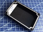
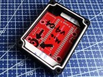
Lid design A – Loose fit
2A. Cut first 10mm foam in lid to position PCB – Turn the lid upside down. Take a 10mm foam strip press down hard across the width of the case to mark it out.
Use the indents to cut to the required shape. length of one short side between the screw holes. We find this easiest by placing and using the scalpel to mark it.
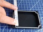

3A. Place 10mm foam in lid to position PCB. Remove one side of backing tape of the first cut strip and stick into place. Do NOT remove the top backing.
Insert the Mic hole Template, then repeat the above process to cut the second foam strip (approx. 7mm wide) at the other end. Cut short so it does not snag the position of the microSD card.
Remove the lower backing and stick into place, do NOT remove the top backing.
Lid design B – Tight fit
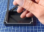
2B. Place 10mm foam in lid to position PCB – Turn the lid upside down. Take a 10mm foam strip and cut to the length of one short side between the screw holes. We find this easiest by placing and using the scalpel to mark it. Remove one side of backing tape and stick into place. Do NOT remove the top backing of the foam strip 1 yet.
Cut a second strip to go on top of the first, bevelling the ends. Test fit, then remove the one side of backing tape of this, and the top of first strip, and fix the second strip over the first.
Repeat the process until you have built up a 9 to 10mm thick pad. This takes 3 strips of 3mm thick, or 5 strips of 1mm thick foam.
Do NOT remove the top backing of last 10mm foam strip.
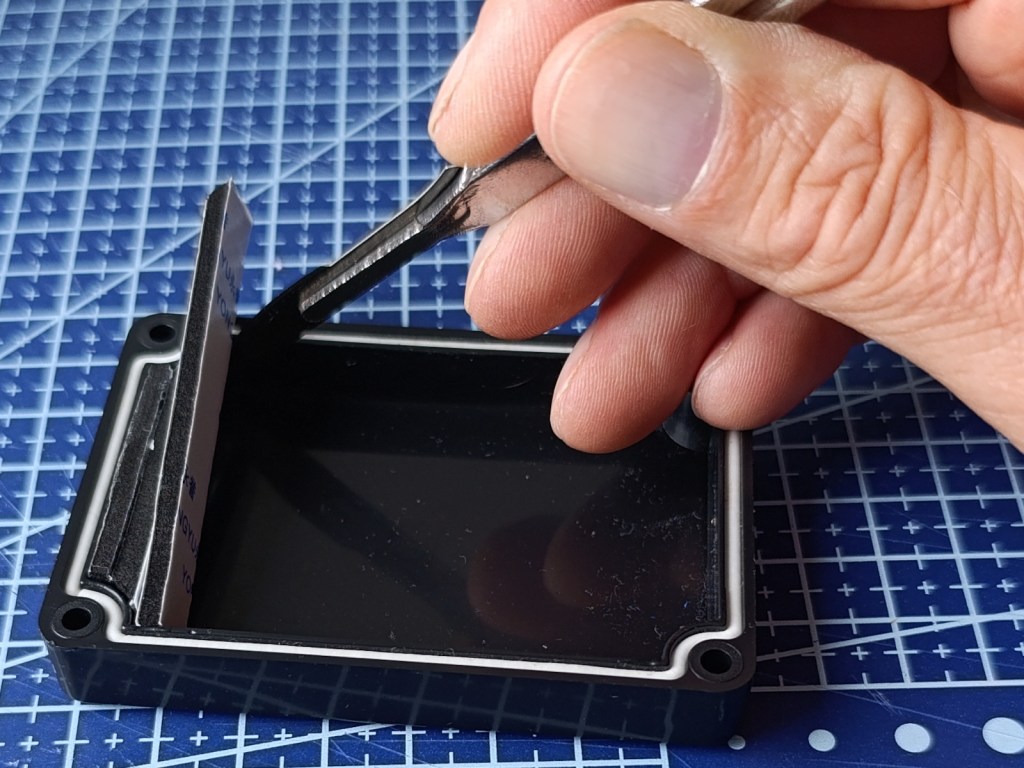
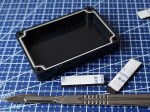
3B. Adding “squashy” foam – From squashy foam (or sponge) cut a strip 10mm x 8mm.
Cut the squashy foam strip so it fits the end of the lid opposite the foam pads. Test fit. If OK, apply 10mm wide double sided tape to hold it in place.
Test fit the PippyG board by push fitting it into the squashy foam first, then lowering the other side. Move onto step 4.

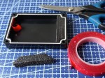

For here on the process for lid designs A and B, tight and loose fit, are identical
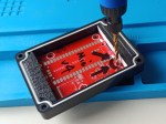
4. Drill Mic Hole – Using a 3mm HSS drill straight down thought the lid, through the correct hole on the mic hole template.
After drilling using a scalpel tidy up the edges of the hole. A slight (1mm) countersinking on the outside of the hole is a good idea.

5. Cut the 80 s/s mesh – The 80 gauge stainless steel mesh is used to absorb the energy of high velocity water drops. Using scissors, cut a 25mm wide strip of the 80 mesh.
From this strip cut a pentagon (house shape), a 25 x 25mm square with a 7mm high Isosceles triangle on top (see photo). The triangle shows which way up, and helps deflect water running down the face of the case.
This 80 gauge pentagon (house shape) becomes your template for the next stage.
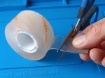
6. Cut mounts – Use the 80 gauge mesh as a template, use scissors to cut two similarly shaped sections of the 25mm double sided mounting tape.
It is FAR easier to do this if you first stick some of the own tapes spare backing to the end of the roll first. If you have made a case before you will already have these backings. But if its your first case it is well worth sacrificing the first 35mm of the tape to get to reusable backings.
Then leaving both backings on, place the mount in position on the case, just missing the screw hole.
Using a marker pen mark the centre of the mic hole on the tape backing. Due the position of the case screws and PippyG this will be off centre.
Then cut a 6mm wide slot out of the bottom (not triangle) sides of the mount, to just above the mic hole marking. This is to allow any water that does get though the mesh to drain out downwards.
Repeat the process for the other tape mount.


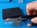
7. Place 400 mesh s/s mesh – Remove (and keep) the backing from one of the mounts, then place it over the mic hole as shown in the photo. Press down firmly. Remove the top layer of the mounting tape backing (this is quite tricky!), again keeping the backing.
Cut a 12mm square out of the 400 gauge stainless steel mesh and place it onto the mount so it is central over the microphone hole. Press down carefully, avoiding the adhesive.
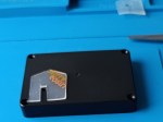
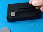
8. Place 2nd mount – Remove the backing from the underside of the second mount and place it exactly over the first mount. Take care, as you one get one go at this.
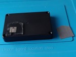
9. Place and glue top mesh – Remove the backing from the top of the second mount, and press the 80 gauge s/s mesh firmly into place. As the mesh is treated, you will find it does not stick that well. Hence we run a bead of superglue around the three top and side edges of the 80 mesh, and allow this to dry thoroughly (make take several hours).
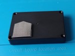
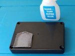
Having finished the lid it is time to move onto the base, which fortunately is a LOT easier!
10. Cut out 8mm foam for base – Using the upturned base of the case push it down into the 8mm thick foam sheet. This will make an indentation that you can cut around with scissors.
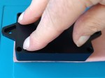

11. Fit foam into base of case – Take the cut piece of 8MM foam and push it upside down into the base of the case, press hard.
Using a scalpel cut out the marked areas, to allow for the six indentations in the base. Then push fit the foam into the base, it should be a tight fit so no need for glue.
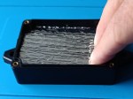


12 – Enlarge case mounting holes – Using a 6mm high speed drill, enlarge the mounting holes in the lugs of the case. This will allow for a wider range of things to be used to locate the case in use, such as bungee cords or thicker zip ties.

Finished type F cases below. It is fairly easy to cover the lid of the type F with Camo tape. The tricky parts are cutting out the slit for the mic hole drain and the screw holes. For best results use a scalpel (and patience!).
The base is a lot harder to cover with camo tape (but possible). However if using the black version of the Type F we are not sure covering the base adds much to the disguise.
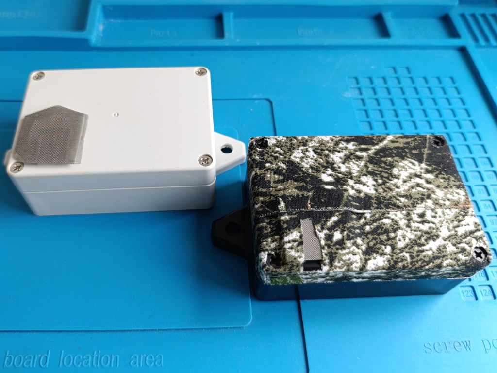
In the above photo the white case uses an alternate shape for the tape mounts, and hence is in a different position. This early version did not work out as well as the version described above with asymmetric tape mounts.

